SMCMR (MARINE) ECU
OVERVIEW
                                                            !!!! IMPORTANT !!!!
In many markets, fitting this product to public road going emission controlled vehicles is illegal. Contact the relevant local authorities to determine the technical and legal requirements of your proposed modification prior to installation.

WARNING: AUTRONIC SMCMR ECUs do not provide the level of redundancy required for failsafe engine operation in manned aircraft. USE FOR ENGINE CONTROL IN MANNED AIRCRAFT IS NOT PERMITTED!!!
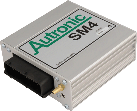
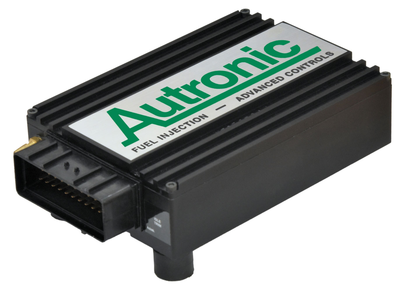
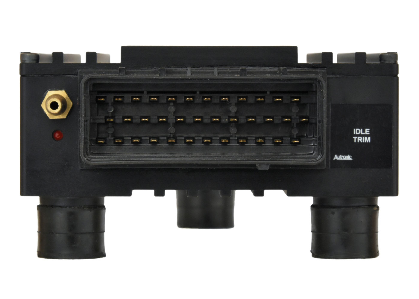
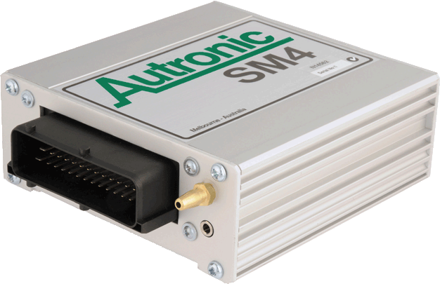
The Autronic SMCMR Sequential Engine Management System is our marinised compact 2nd generation marine engine management system for engine performance upgrades. It was initially developed and then widely adopted for the high output turbo-charged V8 engines of ski boat and marine racers in the USA and Australia. It is our least complex solution for marine applications requiring up to 8 channel sequential fuelling. Simple triggering, a low pin count connector and minimum wiring complexity make for rapid low cost installations and easy maintenance. It caters for the requirements of virtually any spark ignition port injected engine that is not equipped with either drive-by-wire throttle or feedback controlled variable camshafts.
A user friendly Windows software program provides the means of interrogating this engine management system enabling speedy diagnosis and calibration. This program, in combination with intelligence in the management system, allows the user to select the finest calibration detail required to match the application, in minimum time. Calibration sophistication can be tailored to each application.
High output supercharged or turbocharged engines, with either multi point and/or center point injection
Two stroke engines
Engines having uneven firing sequences such as 2 and 4 cylinder "V" configuration motor cycle engines
and V6 motor vehicle engines
‘Full Sequential’ injection for 2 to 8 cylinder engines
In-built Manifold Absolute pressure sensor (options to 450kPa)
Eight Injector outputs (low or high current drive)
Four Ignition outputs without dwell control (standard model only suits CD Ignition or Smart Ignition modules. Requires dwell interface option for use with most OEM ignition systems)
3D Fuel and Ignition maps
Engine calibration tables have up to 32 RPM x 16 Load Sites (= 512 adjustment points) that can be arbitrarily placed by the user
Dedicated output for fuel pump control
One auxiliary output can be defined for boost control, nitrous oxide, staged injectors, camshaft timing (2 position), A/C, fan control, idle valve etc...
Spare Injector Outputs usable for alternate functions
Flat Shift option available
Launch Control option available
Anti-Lag option available
"Autotune" option available
Data Logging & Error diagnostics
Compatible with various Dash / Data loggers
Sealable Billet Aluminium Case for marine applications.
Back
Next
SPECIFICATIONS


IMPORTANT: Please note that this product is intended for high performance motor sport applications and compliance with statutory regulations when used on public roads cannot be guaranteed.


Features.

1.         Eight injector drivers for full sequential operation on engines up to eight cylinders. Staging injection possible in some applications. May be set for 'semi-sequential' operation on engines that have more than 8 cylinders (e.g. 12 cylinder engine using 6 groups of two cylinders). All common port injector types catered for (0.9 ohm to 16 ohm coil resistance) with selectable Low or High current driver. When ordering, request an initial configuration to suit injectors. Drive current selection is field re-configurable.

2.         Four open collector outputs for triggering Capacitor Discharge or Smart Inductive Ignition Modules.

Note: Standard product does NOT provide dwell control (installation of optional dwell control interface module/s is required).

3.         Single coil distributor, twin coil distributor or multicoil distributor-less ignition configurations are possible on most engines.

4.         Fuel pump safety shut-off. Pump stops 3 to 4 seconds after the engine stops.

5.         One auxiliary output in addition to Fuel Pump control. Auxiliary output is PWM and On-Off capable and can be used for Boost Control, Nitrous oxide, Staged Injectors, Camshaft timing (2 position), Cooling Fan control, Charge Cooling control (Water Spray or intercooler fan), Idle valve, Fuel Used Pulse, Gear Shift Light, etc...

6.         Spare Injector Outputs can be used as additional On-Off Outputs.

7.         User choice of Manifold absolute pressure or Throttle position as Engine load input. Internal absolute pressure sensor for simplified installation 0 to 200 kPa (0 to 29.4 PSI) and 0 to 300 kPa (0 to 44.1 PSI) available from stock. 0 to 450 kPa (0 to 66.1 PSI) available on request.

8.         Autronic ‘Mass-flow determination method’ simplifies fuel delivery calibration, especially for multi-butterfly or variable inlet geometry engines equipped with forced induction. This method, combined with other measures, ensures precise fuel delivery matching, irrespective of altitude.

9.         Compensation of engine control parameters for engine operation over a wide altitude range (fuel delivery, ignition timing and boost pressure).

10.      Unique transient calibration strategy allows accurate control of fuel delivery under both acceleration and deceleration.

11.      Direct connect a narrow band O2 sensor for closed loop emissions control, or a compatible wide band Air-fuel ratio meter (e.g. Autronic MAFM1) for full range engine tuning.

12.      Autronic ‘Autotune’ self-tune software feature for air-fuel ratio calibration requiring minimal user intervention (compatible with firmware versions from v1.13).

13.      Closed loop (feedback) boost pressure control for turbocharged engines with calibration curve.

14.      Closed loop (feedback) idle speed control.

15.      Adaptive learning (with memory) to minimize the number of user setups required and to provide optimal control of air/fuel ratio, boost pressure and idle stability.

16.      Precise compensation for injector dead-time and non-linearity. Large library of predefined compensations for popular injector types.

17.      Precise spark advance control strategy for both static and dynamic operating conditions.

18.      User selectable spark and fuel delivery strategies for abnormal engine operating conditions (e.g. over heated or over boosted) that allow continued engine use with reduced risk of engine damage.

19.      Comprehensive limp-home functions with user selectable default settings that, whenever possible, ensure engine operation can continue after sensor failure has occurred.

20.      Coolant temperature dependent Rev Limiter with soft characteristic that uses a combination of fuel delivery and spark control.

21.      Flat Shift & Anti-Lag (Turbo boost enhancement) are available (depending on Firmware version fitted).

22.      Diagnostic/Error indicator light with memory for reporting sensor or ECU fault conditions. Ideal for detection of intermittent fault conditions. Error history information is also accessible from P.C. screen.

23.      User configurable internal data logging of up to 17 channels with the selected channels being sampled as fast as 50 times a second. 24k bytes of non-volatile memory. Peak capture feature aids detection of over-rev, over-boost and over-temperature conditions.

24.      Serial data port can be used in a bi-directional communication mode for P.C. calibration, monitoring and data logging, or in unidirectional mode for data streaming output to a Dash / Data logger. Remote adjustment and/or monitoring are possible if Radio modems are added to the serial link.

25.      Simultaneous and independent operation of the internal data logger and serial port data link is allowed.

26.      Compatible with optional No.1 cylinder spark plug pick-up interface unit that allows sequential injector operation on engines equipped with distributor ignition, without the need for separate crank/camshaft sensors or a special multi-sensor distributor.

27.      Sealable Billet Anodized Aluminium Case.

Note: The above list describes the product family capability. Individual product feature set depends upon firmware version fitted. See ‘SMC ECU FIRMWARE VERSION - FEATURE MATRIX’ document.


Interface Requirements.

INPUTS
Sensors:

1.     Crankshaft position input. Hall Effect pickup (use optional Reluctor interface for compatibility with magnetic reluctor type pickups)

2.     No.1 cylinder reference. Hall Effect pickup  (use optional Reluctor interface for compatibility with magnetic reluctor type pickups)

3.     Digital Pulse I/P for connection of Digital Air /flow meter (Requires additional hardware and compatible  firmware version)

4.     Manifold pressure (Internal to ECU)

5.     Barometric pressure derived from Manifold pressure sensor

6.     Throttle position

7.     Intake air temperature

8.     Engine coolant temperature

9.     Exhaust oxygen sensor (or optional Air/Fuel Ratio meter for wide band measurement)

Switches:

1 x Switch I/P (Switch to Ground)

Adjustments:

1 x Overall / Idle mixture adjustor. (Configurable, internal to ECU and screwdriver adjustable from outside)


  OUTPUTS

8 x injector drivers:

·       User selectable 4A/1A or 2A/0.5A Peak/Hold switching type

·       Spare Injector Outputs usable for alternate functions


(Note: Early SMC production. ECUs were fitted with fixed current peak/hold drivers. These variants can only have injector driver current rating changed by performing complete driver replacement. The AUTRONIC service facility can perform this service, subject to drive availability)

4 x ignition outputs:
Each are open collector output type compatible with:

·       ‘Smart’ Inductive high energy ignitions that have internal dwell control

·       Autronic Capacitor Discharge Ignitions

·       Other capacitor discharge ignitions e.g. MSD 6A etc...


(Note: The SMC ECU is primarily intended for extreme performance applications and is best suited for use with capacitor discharge ignitions. Optional dwell interface module/s can be installed that will provide compatibility with non-dwell controlled inductive high energy ignition systems)

Fuel Pump:

·       Dedicated Fuel pump/injector fuel shut off. For safety relay control


Auxiliary:

         1 x Duty Cycle or On-Off O/P (1A Open collector) suitable for:

·       Engine Cooling Fan relay control

·       Idle speed actuator (variable duty cycle type)

·       Turbocharger waste gate control duty cycle valve (suits Autronic low & large high capacity &  most OEM types)

·       Spare variable PWM output with user define characteristic

·       Spare On/Off output with user define characteristic

·       Fuel Used Pulse output (for trip computer function)


SERIAL I/O


·       RS232 communication port for connection to P.C., Dash or Data logger


SOFTWARE COMPATIBILITY

·      SMC firmware versions v1.10 to v2.00

Software available for P.C.s running Win XP, Vista, Win7 & Win8 32 & 64 bit (requires x86-32bit code support), & MS-DOS


·    Early SMC to firmware versions to v1.08

Software only available for P.C.s running MS-DOS only (Recommend ECU firmware update to >= v1.10)


Specifications

Microcomputer

.

Intel 16 bit running @ 16MHz

Supply Voltage

Normal operation
Safe limits

6.2V to 23V DC continuous
+/- 24V (5 min)
+/- 80V alternator load dump (0.5 SEC)
+/- 1000V inductive spike (10 μSEC)

Current Drain

@ Standby (Ign off)

@ Engine idle
@ Max Engine Load

< 1 mA


< 1 Amp
< 16 Amp (less depending on injector type and number)

Outputs

Injector

8  x User selectable 4A/1A or 2A/0.5A     (Peak/Hold)

Ignition

4 x Open collector 1A (standard product does not have dwell control)

PWM / On-Off

1 x Open collector 1A

Inputs

Digital Pulse

1 x Crankshaft

1 x Camshaft

1 x Digital Air /flow meter (special version only)

Switch

1 x Switch to Gnd

Analog

1 x Throttle Position

1 x Manifold Air Intake Temperature

1 x Engine Coolant Temperature

1 x O2 Sensor or Air/Fuel Ratio Meter

Serial Data

1 x RS232

Operating Temperature Range

Min
Max

- 40 deg C
+ 85 deg C

Engine Cylinder Number Settings

Number of cylinders

1, 2, 3, 4, 5, 6, 7, 8, 10, 12, 14 & 16

Engine RPM Range

0 to 30,000 RPM
0 to 16,000 RPM
0 to 15,000 RPM

Engines up to 4 cylinders


Engines 5 to 8 cylinders


Engines 10 to 16 cylinders

Injection Duration Timing

Min
Max
Accuracy
Setting resolution

0.7 msec
30 msec
+/- < (10 μSEC + 1%)
0.1% approx

Injection Timing

Range
Accuracy
Setting resolution

0 to 720 deg (crank angle)
+/- < (1.4 deg + 0.3 mSEC)
2.8 deg

Ignition Timing

Advance range
Accuracy
Setting resolution

0 to 45 deg (crank angle)
+/- 0.2 deg (crank angle)
0.5 deg (crank angle)

Fuel Delivery and Ignition Mapping

No. Load sites
No. RPM sites

16 (max) both Load and RPM sites
32 (max) are freely selectable

Size

L * W * H

155 * 109 * 43 mm
179 * 109 * 62 mm (overall, including mounts & connector)

Weight

 .

0.80 kg

External

Connectors

36 way 'AMP'

Water & dust sealed

Serial Data

3.5mm stereo  (in Wiring Loom)


APPLICATION INFORMATION
SMC FIRMWARE FEATURES Size
  SMC Firmware Version - Feature Matrix 34KB
SMC CONFIGURATION SHEETS
  SMC v1.05 Configuration Mode Sheet 22KB
  SMC v1.06 Configuration Mode Sheet 23KB
  SMC v1.07 Configuration Mode Sheet 27KB
  SMC v1.09 Configuration Mode Sheet 23KB
  SMC v1.10 Configuration Mode Sheet 24KB
  SMC v1.11 Configuration Mode Sheet 27KB
  SMC v1.12 Configuration Mode Sheet 27KB
  SMC v1.13 & v 1.14 Configuration Mode Sheet 28KB
  SMC v1.15 Configuration Mode Sheet 28KB
  SMC v1.16 Configuration Mode Sheet 25KB
  SMC v1.18 Configuration Mode Sheet 28KB
  SMC v1.18_2 Configuration Mode Sheet 29KB
  SMC v1.19 Configuration Mode Sheet 27KB
  SMC v1.90 & V1.91 Configuration Mode Sheet 28KB
  SMC v1.92 to v1.94 Configuration Mode Sheet 29KB
  SMC v1.99 Configuration Mode Sheet 18KB
  SMC v1.99_2 Configuration Mode Sheet 19KB
  SMC v1.99_3 Configuration Mode Sheet 19KB
  SMC v2.00 Configuration Mode Sheet 20KB
Note: Firmware main revision level can be identified using P.C. software (eg: v1.15 vs v1.16). Firmware sub revision level (eg: v1.18 vs v1.18_2) cannot be distinguished using P.C. software. External ECU labelling, CPU labelling or inscription must be used for identification.
SMC WIRING DIAGRAMS
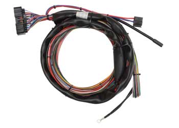
  SMC std loom                          (rev C Loom:  Supplied in kit from 1996. Suits all SMC ECUs) 343KB
  SMC early loom                        (Early Loom: Supplied in kit pre-1996. Only suits pre-1996 ECUs) 343KB
  SMC twin relay wiring                (Works to lower battery voltage. Better for multiple fuel pumps.
                                                  Suits all SMC ECUs )
295KB
  SMC early twin relay wiring        (Works to lower battery voltage. Better for multiple fuel pumps.
                                                  Only suits pre-1996 ECUs)
295KB
PURCHASE OPTIONS
SMCMR MARINE
SEQUENTIAL ENGINE MANAGEMENT SYSTEM

(also available as a loom or connector set kit with air temperature sensor, data lead and fuel pump relay)
SMC Std loom (3.0 metre)
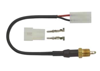
Autronic Air Intake
temperature sensor
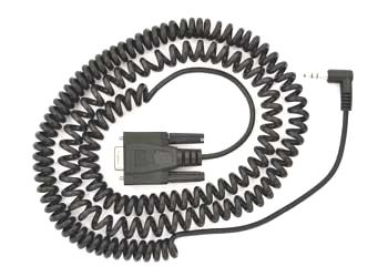
Standard DB9 Data Lead length 5m (Suits most laptops/PCs and USB to Serial adaptors)
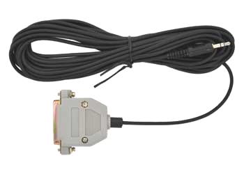
Old style DB25 Data Lead length 5m (Suits older type RS232 ports only)
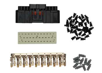
SMC connector set
                                                            !!!! IMPORTANT !!!!
In many markets, fitting this product to public road going emission controlled vehicles is illegal. Contact the relevant local authorities to determine the technical and legal requirements of your proposed modification prior to installation.

WARNING: AUTRONIC SMC ECUs do not provide the level of redundancy required for failsafe engine operation in manned aircraft. USE FOR ENGINE CONTROL IN MANNED AIRCRAFT IS NOT PERMITTED!!!
  
  When ordering specify...


Manifold pressure sensor rating 200 or 300 kPa absolute (450 kPa gauge, on special order)
Injector drivers. Either 2/0.5 AMP or 4/1 AMP (Peak/Hold)
Firmware revision or features required
 
© 2023 Aubert Electronics Pty Ltd
Search Site