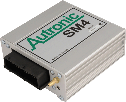
General purpose Ignition modules suitable for use with all AUTRONIC ECUs that are equipped with internal dwell control. Available in single, twin, triple and quad channel versions. They are an excellent choice as replacements for most OEM modules.
See the "Application Info" section for IMPORTANT general application guidelines for these modules, and other ignition modules and coils.
See the "Application Info" section for IMPORTANT general application guidelines for these modules, and other ignition modules and coils.
OVERVIEW
APPLICATION INFORMATION
1.
Each ignition module MUST be mounted onto an aluminium heat sink. Minimum dimensions:
Thickness: 6mm.
Area: Single channel module 70 sq cm
Multiple channel module 100 sq cm
Apply heat conductive paste to mounting face prior to installation.
Thickness: 6mm.
Area: Single channel module 70 sq cm
Multiple channel module 100 sq cm
Apply heat conductive paste to mounting face prior to installation.
2.
Module ground connection should be short, and connected directly to the chassis. Add a thin braided lead interconnect between the chassis in the vicinity of the module, and the engine block.
3.
Simultaneous operation of the outputs of a multi channel ignition module can result in module failure due to current or thermal overload, and should be avoided. Therefore, twin plug distributor or direct fire ignition, or rotary engine ignition require at least two ignition modules.
4.
ECU dwell time calibration MUST be set correctly for the application. Too little dwell will cause engine misfire. If set too large, module and/or coil damage will result. The most common symptom of excessive dwell is severe overheating of the ignition module that is the result of output stage saturation loss.
Correct dwell time calibration will typically cause coil and module temperature rises above ambient of less than 20 deg C at low RPM and less than 30 deg C at high RPM.
Dwell calibration is easily determined using an oscilloscope. Primary circuit voltage should be monitored, and dwell time must be set below the value that causes the ignition module output stage to come out of saturation. A 0.1Ω or preferably 0.05Ω resistor can be inserted in series with the module's ground connection in order to monitor the primary circuit current.
Dwell time should be set to achieve the lesser of the module and coil current ratings. BOSCH modules available from AUTRONIC have a maximum current rating of 10A. If current ratings are unknown, adjust dwell to a value that avoids coil magnetic circuit saturation, loss of output stage saturation and excessive component heating. Peak current in the range 4A to 8A is usually required. Since dwell time requirement is supply voltage dependent, calibration must be determined for the full operating voltage range.
TYPICAL DWELL CALIBRATION
| Dwell calibration for 7.0A peak current | ||||
| Bosch 2 x Double ended coil 0 221 503 407 & Bosch 3 x Double ended coil 0 221 503 002 | Bosch Pencil coil 0 221 504 460 |
Bosch HEC715 |
Bosch MEC717 |
|
| Supply voltage (volts) | Dwell time (mSEC) | Dwell time (mSEC) | Dwell time (mSEC) | Dwell time (mSEC) |
| 6.0 | 13.3 | 14.4 | 19.3 | 17.6 |
| 8.0 | 6.6 | 4.10 | 8.9 | 6.5 |
| 10.0 | 4.5 | 2.68 | 5.9 | 4.2 |
| 12.0 | 3.5 | 2.02 | 4.2 | 3.1 |
| 16.0 | 2.4 | 1.35 | 2.9 | 2.1 |
| 20.0 | 1.8 | 1.02 | 2.1 | 1.5 |
Inductive Ignition Systems are designed to produce high voltage on the ignition coil primary and secondary terminals only when triggering occurs. High voltage should not normally be present when the engine is not running. Nevertheless, users should ALWAYS assume that high voltage could be present and that the ignition system is ALWAYS DANGEROUS.
Contact with the primary or secondary ignition circuits when high voltage is present, will result in SERIOUS PERSONAL INJURY OR DEATH.
During installation, all ignition system primary and secondary circuitry should be insulated to prevent possible human contact.
Contact with the primary or secondary ignition circuits when high voltage is present, will result in SERIOUS PERSONAL INJURY OR DEATH.
During installation, all ignition system primary and secondary circuitry should be insulated to prevent possible human contact.
DISCONNECT THE VEHICLE BATTERY AND IGNITION MODULE PRIOR TO COMMENCING WORK ON ANY IGNITION SYSTEM COMPONENTS.

These ignition system components do not provide the level of redundancy required for failsafe engine operation in manned aircraft.
USE FOR ENGINE IGNITION IN MANNED AIRCRAFT IS NOT PERMITTED!!!
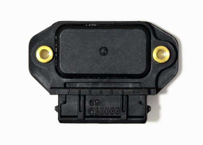
0 227 100 124 Single Channel Ignition Module
0 227 100 203 Triple Channel Ignition Module
Suits Single, Dual & Triple Ignition Modules
Suits Single, Dual & Triple Ignition Modules
0 227 100 211 Quad Channel Ignition Module
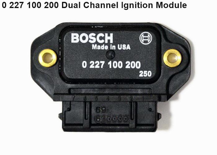
0 227 100 200 Dual Channel Ignition Module
1x Reqd. for Quad Ignition Module
1x Reqd. for Quad Ignition Module


")
")
")
")
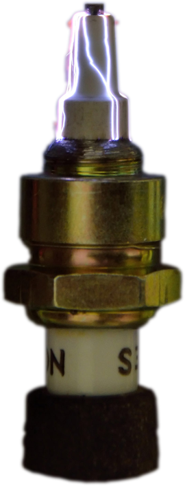
INDUCTIVE IGNITION


© 2023 Aubert Electronics Pty Ltd