HALL EFFECT TRIGGERS
Hall Effect sensors are an ideal choice for automotive applications requiring rotation measurement. These sensors are compatible with all Autronic Engine management systems. The Gear Tooth sensors are suited to crankshaft and camshaft rotation measurement, and for tailshaft, drive shaft or wheel speed measurement. The Hall Effect vane switch is a commonly used solution for distributor or camshaft rotation measurement. They are extremely vibration resistant, tolerate to moisture and temperature extremes, and exhibit excellent long term reliability
OVERVIEW
APPLICATION INFORMATION
NOTES:
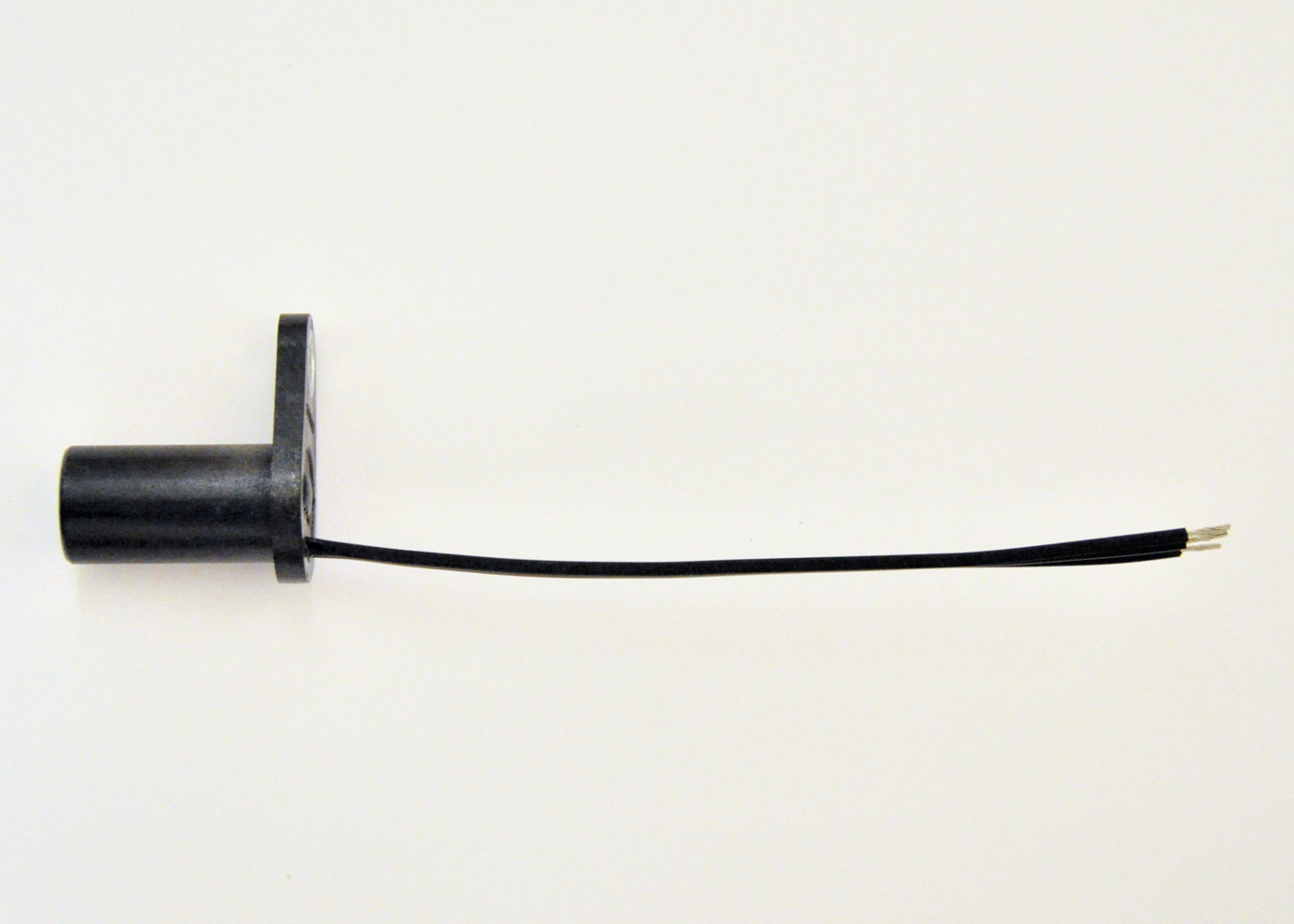
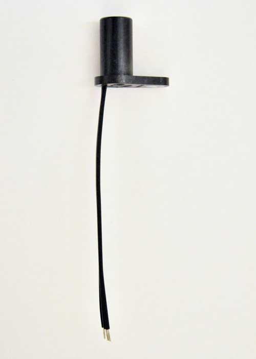
| HALL EFFECT GEAR TOOTH SENSOR - 1GT101DC | |
| Supply Voltage | 4.5 to 24.0 volts DC (reverse polarity & transient protected to +/-30 volts) |
| Supply current (@ 25degC) | < 20mA |
| Output type | Sink (< 0.4 volts DC @ 40mA max) |
| Operating temperature range | -40 to +150 degC |
| Tooth height | > 5 mm 2 |
| Tooth width | > 2.5 mm 2 |
| Tooth spacing | > 10 mm 2 |
| Tooth thickness | > 6 mm 2 |
| Tooth to Sensor gap | 1 to 2 mm 2 |
| Dimensions | Body dia = 17.86 +/-0.13 mm Body length = 36.37 +/- 0.15 mm |
| Connections | Black/Red = + Supply Black/White = Signal O/P Black = Supply gnd |
1.
Trigger wheel or cup tooth dimensions are interdependent. Refer to honeywell.com Hall effect vane sensor documentation for recommendations.
2.
The trigger wheel or cup material must be a 'soft" magnetic iron or steel. Unannealed 1010 - 1018 or lower carbon cold rolled steel is suitable. Only ferrous materials that do not retain any residual magnetism are suitable.
3.
Either or both tooth edges produce accurate triggering. Set the engine management system for RISING edge triggering to utilize the leading edge of the tooth. FALLING edge triggering selects the trailing tooth edge. Select BOTH when the application requires both leading and trailing edges.
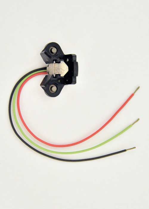
| HALL EFFECT VANE SENSOR - 2AV54 | |
| Supply Voltage | 4.5 to 24.0 volts DC (reverse polarity & transient protected to +/-80 volts) |
| Supply current (@ 25degC) | < 22mA |
| Output type | Sink (40mA max) |
| Operating temperature range | -40 to +150 degC |
| Switching point deviation with temperature (relative to 25 degC) | < +/-0.05 mm |
| Vibration | 45g Mil-Std-202. Method 204, Condition E |
| Recommended Tooth width | > 12 mm 1 |
| Recommended Tooth gap | > 9.5 mm 1 |
| Recommended Tooth length | > 10.5 mm 1 |
| Tooth thickness | 0.8 mm < t < 1.5 mm 1 |
| Connections | Red = + Supply Green = Signal O/P Black = Supply gnd |
NOTES:
IMPORTANT !!! Hall Effect sensors like all electronic sensors can be affected by electromagnetic interference. Spark discharges at the spark plugs and between the rotor button and distributor cap produce such interference. Use quality radio frequency suppressed high tension leads to minimize emission of troublesome interference.
WARNING !!! All Hall Effect sensors types are permanently damaged or destroyed if overheated by friction resulting from contact with any fast moving object. Ensure that an air gap is always present.
WARNING !!! All Hall Effect sensors types are permanently damaged or destroyed if overheated by friction resulting from contact with any fast moving object. Ensure that an air gap is always present.
1.
Mount the sensor in a non-ferrous holder that supports its body, and use the rear lug for sensor retention. Avoid having ferrous material within 2mm of the sensor. Do not use the rear lug for mounting.
2.
Trigger wheel tooth and sensing gap dimensions are interdependent. Refer to honeywell.com Hall effect gear tooth sensor documentation for recommendations.
3.
The trigger wheel material must be a 'soft" magnetic iron or steel. Unannealed 1010 - 1018 or lower carbon cold rolled steel, cast iron or cast steel are generally used. Only materials that do not retain any residual magnetism are suitable.
4.
High tensile bolts retain residual magnetism that can affect the operation of this sensor. They will NOT work as teeth when mounted into a non-ferrous wheel. Installation into a massive ferrous base, such as an iron flywheel, is allowed since the effect of any residual magnetism is almost eliminated. The heads of socket head cap screws can be successfully employed as teeth on steel flywheels. In all cases the flywheel base material must comply with item 2 (above) specifications.
5.
Use with flywheels that contain magnets for an alternator charging system is not recommended.
6.
At low RPM the switching point of the tooth trailing edge is NOT guaranteed (especially with wide teeth). For applications where accurate trigger point positioning is a requirement (eg. crankshaft or camshaft sensing for engine management) ensure that only the leading edge of the tooth is used for sensing by selecting FALLING edge triggering.
7.
Following each rotation commencement or initial power-up, the sensor will not detect a tooth until after a tooth gap has passed under the sensor.
8.
This gear tooth sensor is not a static type sensor. It will not reliably detect the presence of a stationary object.
Genuine Honeywell product
Genuine Honeywell product
HALL EFFECT GEAR TOOTH SENSOR
HALL EFFECT VANE SWITCH


© 2023 Aubert Electronics Pty Ltd