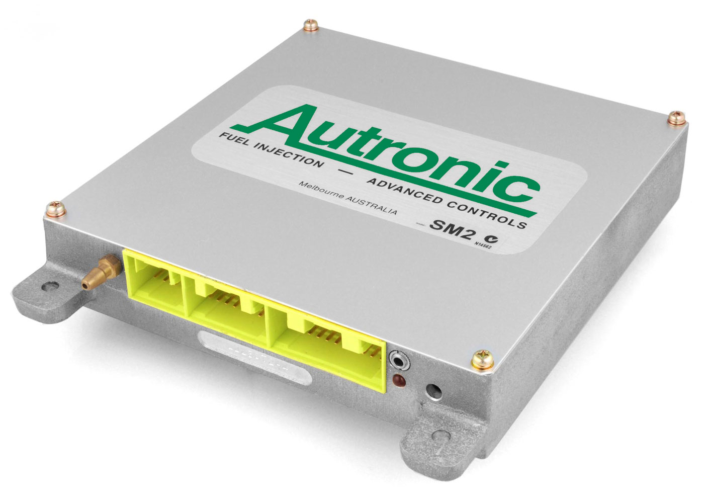
SM2 ECU
LEGACY
PRODUCT
PRODUCT
OVERVIEW
LEGACY PRODUCT NOTIFICATION
This 1st generation engine management system SM2 is now designated as a legacy product. It is not recommended for new designs, instead please consider using our later generation products, such as SM3 or SM4. This product is still available to customers such as those wishing to maintain or replicate existing installations. NEW SM2 ECUs can still be purchased to match the specifications of almost any of the product’s variants. HISTORIC RACE CARS can be maintained with new replacement components that exactly match the specifications of those originally used. Autronic will continue to offer upgrade, modification and repair services for SM2. Its P.C. calibration software continues to be updated with calibration support for recently released injectors.
•
‘Full Sequential’ injection for 2 to 8 cylinder engines
•
In-built Manifold Absolute pressure sensor (options to 450kPa)
•
Eight Injector outputs (low or high current drive)
•
Four Ignition outputs
•
3D Fuel and Ignition maps
•
Engine calibration tables have up to 32 RPM x 16 Load Sites (= 512 adjustment points) that can be arbitrarily placed by the user
•
Seven Auxiliary outputs in addition to fuel pump control
•
Auxiliary outputs can be defined for boost control, nitrous oxide, staged injectors, camshaft timing (2 position), A/C, fan control, idle valve etc...
•
Traction Control option available
•
Flat Shift option available
•
Launch Control option available
•
Anti-Lag option available
•
"Autotune" option available
•
Data Logging & Error diagnostics
•
Compatible with various Dash / Data loggers
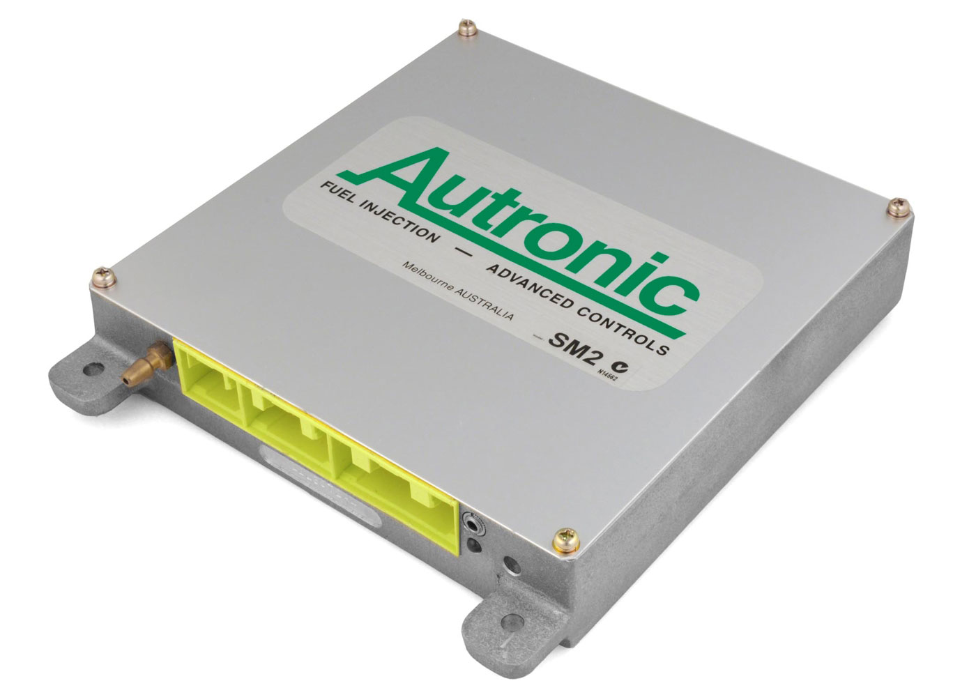
The Autronic SM2 Sequential Engine Management System offers versatile engine management for engine performance upgrades. It caters for the requirements of virtually any spark ignition port injected engine that is not equipped with either drive-by-wire throttle or feedback controlled variable camshafts.
A user friendly Windows software program provides the means of interrogating this engine management system enabling speedy diagnosis and calibration. This program, in combination with intelligence in the management system, allows the user to select the finest calibration detail required to match the application, in minimum time. Calibration sophistication can be tailored to each application.
•
High output supercharged or turbocharged engines, with either multi point and/or center point injection
•
Rotary (2 rotor) and two stroke engines
•
Engines having uneven firing sequences such as 2 and 4 cylinder "V" configuration motor cycle engines
and V6 motor vehicle engines
and V6 motor vehicle engines
!!!! IMPORTANT !!!!
In many markets, fitting this product to public road going emission controlled vehicles is illegal. Contact the relevant local authorities to determine the technical and legal requirements of your proposed modification prior to installation.
WARNING: AUTRONIC SM2 ECUs do not provide the level of redundancy required for failsafe engine operation in manned aircraft. USE FOR ENGINE CONTROL IN MANNED AIRCRAFT IS NOT PERMITTED!!!
SPECIFICATIONS
LEGACY
PRODUCT
PRODUCT
APPLICATION INFORMATION
LEGACY
PRODUCT
PRODUCT
| SM2 FIRMWARE FEATURES | Size |
| SM2 Firmware Version - Feature Matrix | 44KB |
| SM2 CONFIGURATION SHEETS | |
| SM2 v1.03 to v1.07 Configuration Mode Sheet | 19KB |
| SM2 v1.34 & v1.35 Configuration Mode Sheet (v1.35 has no Traction Control feature) | 24KB |
| SM2 v1.36 Configuration Mode Sheet | 24KB |
| SM2 v1.37 & v1.37_3 Configuration Mode Sheet | 26KB |
| SM2 v1.37_2 Configuration Mode Sheet | 26KB |
| SM2 v1.38 Configuration Mode Sheet | 26KB |
| SM2 v1.40 Configuration Mode Sheet | 24KB |
| SM2 v1.40_2 & v 1.40_3 Configuration Mode Sheet | 25KB |
| SM2 v1.41 Configuration Mode Sheet | 27KB |
| SM2 v1.43 Configuration Mode Sheet | 27KB |
| SM2 v1.44 Configuration Mode Sheet | 25KB |
| SM2 v1.45 & v1.46 Configuration Mode Sheet | 27KB |
| SM2 v1.47 Configuration Mode Sheet | 27KB |
| SM2 v1.48 Configuration Mode Sheet | 27KB |
| SM2 v1.49 & v1.49_2 Configuration Mode Sheet | 27KB |
| SM2 v1.90 & v1.91 Configuration Mode Sheet | 28KB |
| SM2 v1.92 Configuration Mode Sheet | 28KB |
| SM2 v1.93 Configuration Mode Sheet | 27KB |
| SM2 v1.93_2 Configuration Mode Sheet | 28KB |
| SM2 v1.93_3 Configuration Mode Sheet | 27KB |
| SM2 v1.93_4 Configuration Mode Sheet | 27KB |
| SM2 v1.94 Configuration Mode Sheet | 28KB |
| SM2 v1.95 Configuration Mode Sheet | 27KB |
| SM2 v1.95_3 Configuration Mode Sheet | 27KB |
| SM2 v1.99 Configuration Mode Sheet | 27KB |
| SM2 v1.99_2 Configuration Mode Sheet | 27KB |
| Note: Firmware main revision level can be identified using P.C. software (eg: v1.40 vs v1.38). Firmware sub revision level (eg: v1.40_2 vs v1.40_3) cannot be distinguished using P.C. software. External ECU labelling, CPU labelling or inscription must be used for identification. | |
| SM2 WIRING DIAGRAMS | |
| SM2 std loom | 343KB |
| SM2 STANDARD TRIGGERING | |
| SM2 - Distributor ignition, 4 cylinder triggering diagram | 150KB |
| SM2 - Distributor ignition, 8 cylinder triggering diagram | 172KB |
When ordering specify...
PURCHASE OPTIONS
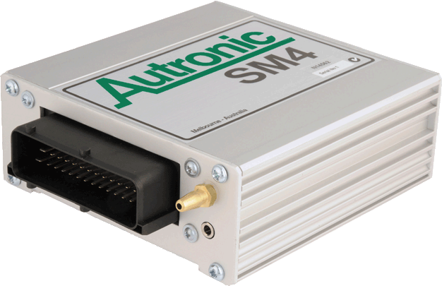
SM2
SEQUENTIAL ENGINE MANAGEMENT SYSTEM
(also available as a loom or connector set kit with air temperature sensor, data lead and fuel pump relay)
SEQUENTIAL ENGINE MANAGEMENT SYSTEM
(also available as a loom or connector set kit with air temperature sensor, data lead and fuel pump relay)
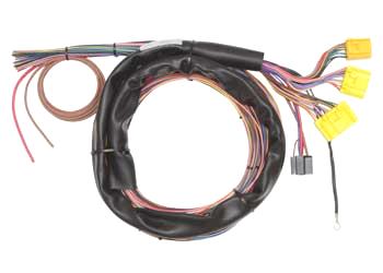
SM2 Std loom (3.0 metre)
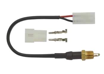
Autronic Air Intake
temperature sensor
temperature sensor
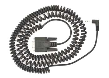
Standard DB9 Data Lead length 5m (Suits most laptops/PCs and USB to Serial adaptors)
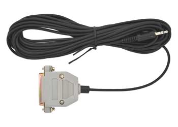
Old style DB25 Data Lead length 5m (Suits older type RS232 ports only)
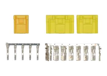
SM2 connector set
•
Manifold pressure sensor rating. 200 or 300 kPa absolute (450 kPa gauge special order)
•
Injector drivers. Either 2/0.5 AMP or 4/1 AMP (Peak/Hold)
•
Firmware revision or features required
LEGACY PRODUCT NOTIFICATION
This 1st generation engine management system SM2 is now designated as a legacy product. It is not recommended for new designs, instead please consider using our later generation products, such as SM3 or SM4. This product is still available to customers such as those wishing to maintain or replicate existing installations. NEW SM2 ECUs can still be purchased to match the specifications of almost any of the product’s variants. HISTORIC RACE CARS can be maintained with new replacement components that exactly match the specifications of those originally used. Autronic will continue to offer upgrade, modification and repair services for SM2. Its P.C. calibration software continues to be updated with calibration support for recently released injectors.
LEGACY
PRODUCT
PRODUCT
!!!! IMPORTANT !!!!
In many markets, fitting this product to public road going emission controlled vehicles is illegal. Contact the relevant local authorities to determine the technical and legal requirements of your proposed modification prior to installation.
WARNING: AUTRONIC SM2 ECUs do not provide the level of redundancy required for failsafe engine operation in manned aircraft. USE FOR ENGINE CONTROL IN MANNED AIRCRAFT IS NOT PERMITTED!!!
In many markets, fitting this product to public road going emission controlled vehicles is illegal. Contact the relevant local authorities to determine the technical and legal requirements of your proposed modification prior to installation.
WARNING: AUTRONIC SM2 ECUs do not provide the level of redundancy required for failsafe engine operation in manned aircraft. USE FOR ENGINE CONTROL IN MANNED AIRCRAFT IS NOT PERMITTED!!!


© 2023 Aubert Electronics Pty Ltd