In many markets, fitting this product to public road going emission controlled vehicles is illegal. Contact the relevant local authorities to determine the technical and legal requirements of your proposed modification prior to installation.
WARNING: AUTRONIC SM4 ECUs do not provide the level of redundancy required for failsafe engine operation in manned aircraft. USE FOR ENGINE CONTROL IN MANNED AIRCRAFT IS NOT PERMITTED!!!
See "SM4DC Dual Calibration"
See "SM4MR Marine ECU"
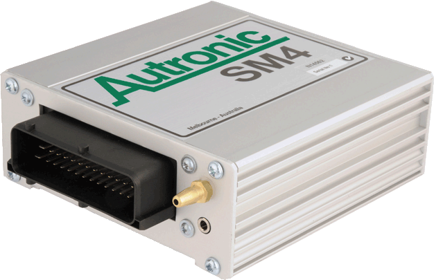
AUTRONIC SM4 ECU Specifications
|
Microcomputer |
|
Intel 16 bit 20MHz |
|
Power Supply - Voltage |
Normal operation Operational limits
Survival limits |
12v to 15v DC 6.2v to 18v DC continuous
+/- 23v (5 minutes) Outside +/-23 volt limits: 80A (Load Dump <20mSEC) 100A (Inductive surge <1mSEC) -10A (Inductive surge <100uSEC) |
|
Power Supply - Current |
Off ECU only At Idle At maximum Load |
< 1mA < 0.2 A < 1.0 A < 16 A (depending on injector type) 2 |
|
Operating temperature range |
Limits |
-40°C to +85°C |
|
Storage temperature range |
Limits |
-40°C to +105°C |
|
Engine Cylinder selections |
Number of cylinders Types |
1, 2, 3, 4, 5, 6, 7, 8, 10, 12, 14, 16 2 stroke (360° cycle), 4 stroke (720° cycle) & Rotary |
|
Engine operation ranges1 |
1 to 4 cylinders 5 or 6 cylinders 7 or 8 cylinders 10 to 16 cylinders |
0 to 28000 RPM 0 to 18000 RPM 0 to 14000 RPM 0 to 12000 RPM |
|
Hardware Drivers |
Injectors
Ignition GP Outputs
|
8 (2 x 4 output groups. Each group selectable 4A/1A or 2A/0.5A Peak/Hold) 2 4 Push–Pull 0.8A cont (1A peak) 4 Push-Pull 0.8A cont (1A peak) 4 Open-Collector 1@1A, 2@2.5A, 1@3.5A 2 PWM, up to 1.2kHz, 1@3.5A & 1@5A |
|
Injection Pulse Timing |
Minimum output pulse time Maximum output pulse time Resolution Accuracy |
0.65 msec 50 msec 0.1% approximately < (1% + 10usec) |
|
Injection Phase Timing |
4 stroke Range 2 stroke / Rotary Range Resolution Accuracy |
0 to 717° 0 to 359° 2.8° < (1.4° + 0.3 msec) |
|
Ignition timing |
Timing modes Timing range Resolution Accuracy |
Dwell or Pulse -64° to +63.5° 0.5° 0.3° |
|
Base Fuel & Ignition tables |
RPM sites Load sites |
1 to 32 freely definable 1 to 16 freely definable |
|
Data Logging Memory |
Size |
507 Kbytes or 114 Kbytes |
|
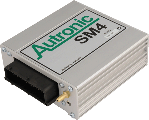
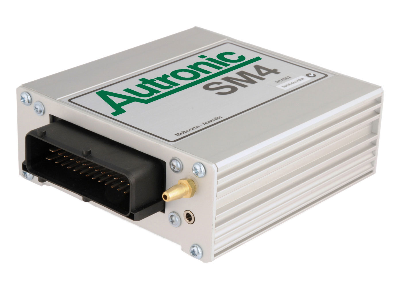
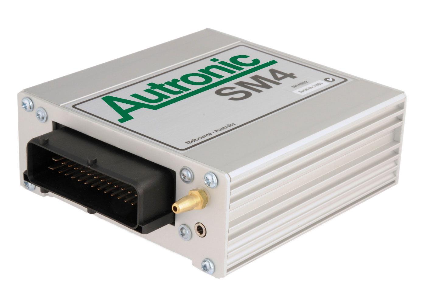
Housing |
L * W * H Type |
130 * 124 * 48 mm (L 144 mm overall) Anodized aluminium |
|
Weight |
|
0.5 kg |
|
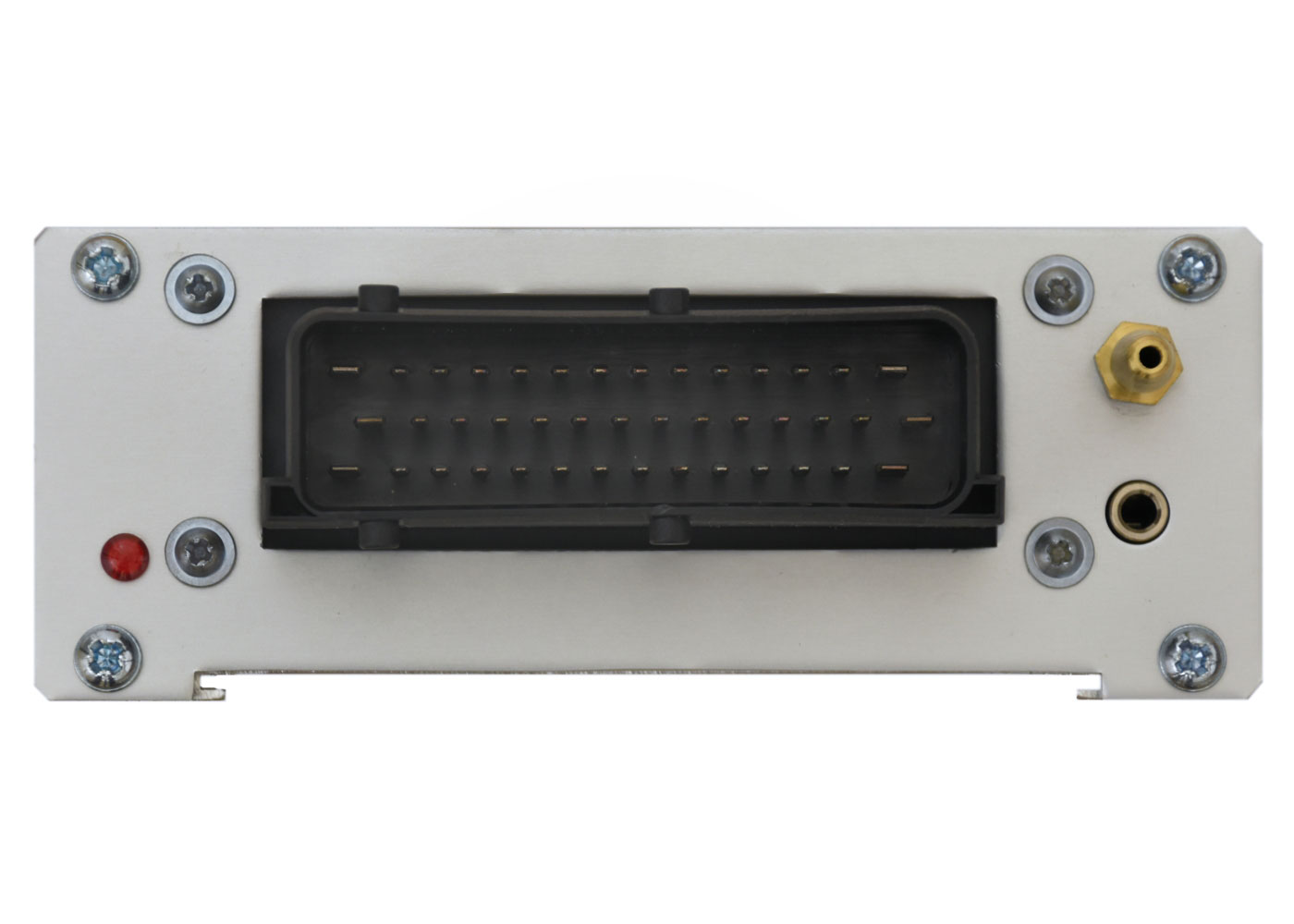
Connectors |
Main connector Communications |
42 way splash & dust proof 3.5 mm stereo Serial Data |
Notes: 1 2 stroke: 1 to 4 cylinders 0 to 15000 RPM, 5 or 6 cylinders 0 to 12000 RPM, 7 or 8 cylinders 0 to 10000 RPM, 10 to 12 cylinders 0 to 8000 RPM.
2 A high current injector drive version is available on special order. Each group is selectable 8A/2A or 4A/1A (Peak/Hold). Maximum supply current < 20A.
IMPORTANT: Please note that this product is intended for high performance motor sport applications and compliance with statutory regulations when used on public roads cannot be guaranteed.
AUTRONIC SM4 ECU Detailed Features
1. Eight injector drivers for full sequential operation on engines up to eight cylinders. May be set for 'semi-sequential' operation on engines that have more than 8 cylinders (e.g. 12 cylinder engine using 6 groups of two cylinders). Eight arbitrarily positioned injection events per engine cycle are possible with any combination of the 8 outputs firing at each event suits odd fire engines. Staged injection is possible via individual injector trim tables. 3D table mappable control of injection end point timing. All common port injector types catered for (0.6 ohm to 16 ohm coil resistance) with peak and hold output drive current selectable to 2A/0.5A (low) or 4A/1A (high). Independent current selection for 2 groups of 4 injection outputs each. Unused Injector outputs are available for alternate output (up to 7) or alternate switch input (up to 3). A higher current version with injector outputs rated at 8A/2A and 4A/1A (peak/hold) is available on special order.
2. Four push-pull Ignition outputs with 3D mappable dwell or pulse time duration. Suitable for Distributor and Distributor-less inductive, Coil-on-plug and Capacitor Discharge ignition systems. Single coil distributor, twin coil distributor, twin-plug distributor or distributor-less, or multi-coil distributor-less ignition configurations are possible on most engines. Multiplexed output function allows coil per cylinder without waste spark in application beyond 4 cylinders and waste spark beyond 8 cylinders, when used with compatible ignition systems. Unused Ignition outputs are available for alternate output (up to 3).
3. Programmable Crankshaft & Sync inputs selectable for Hall-effect and Magnetic Reluctor sensors. Sensing circuitry adapts to Reluctor signals ranging from 0.8v to 350v peak to peak. Programmable signal filtering reduces the chance of mis-triggering. Trigger decoding logic is compatible with the trigger wheels used by most engine manufacturers. When the Sync input is not required for camshaft sensing, it can be used as a speed input.
4. Three dedicated digital inputs. All are suitable for speed measurement or as switch inputs. Two are capable of being used with the Crankshaft & Sync inputs for camshaft position measurement. One is suitable for the connection of a Digital Airflow meter or Digital Flex-fuel sensor. Also up to 3 unused injector outputs can be used as switch inputs.
5. Two dedicated PWM outputs @ 9.5 to 1200Hz. 1 x Pull-down @ 5 amp, 1 x Pull-down @ 3.5 amp.
6. Eight General Purpose (GP) outputs are On-Off and PWM capable: 1 x Pull-down @ 3.5 amp, 2 x Pull-down @ 2.5 amp, 1 x Pull-down @ 1 amp and 4 Push-Pull @ +/- 1 amp max. The 4 Push-pull outputs are also suitable for a single stepper motor or two H-Bridges, or a single higher current rated H-Bridge when paralleled in pairs.
7. Eleven Pulse width modulators to GP outputs, spare Injector or Ignition O/Ps. Frequency ranges: 8 @ 10Hz only, 3 @ 10 to 500Hz.
8. The outputs of functions including boost control, idle control, nitrous oxide, water injection, staged injectors, tumble valve/s, camshaft timing, A/C, multiple fans, fuel used pulse, fuel pump staging, user define O/P and Error condition &/or Knock indication, General Purpose Controls (GPC see below), etc. can be directed to physical pins or used internally by other functions.
9. User choice of Manifold absolute pressure or Throttle position as Engine load input. Internal absolute pressure sensor for simplified installation. The standard Manifold absolute pressure sensor is continuous rated to 200 kPa (29 PSI) absolute and intermittently to 440 kPa (64 PSI) absolute, and is available from stock. A heavy duty 510 kPa (74 PSI) absolute continuous rated sensor is available on special order. The internal sensor can be used for barometric pressure sensing when an external Manifold absolute pressure sensor is connected (only if the internal sensor is a standard 0 to 200kPa absolute type). Absolute manifold pressure may be derived from a Digital Airflow meter.
10. Dedicated analogue channels for: Battery voltage, Throttle Position sensing, Air Intake, O2, Coolant temperature.
11. The O2 and 2 additional analogue inputs can alternately be used for general purpose analogue measurement or user defined thresholds of switch inputs.
12. Up to 2 sensing thresholds can be set for each analogue INPUT (except the internal Pressure sensor channel) for the digital control of internal functions.
13. Autronic ‘Mass-flow determination method’ Throttle Pressure mapping simplifies fuel delivery calibration, especially for multi-butterfly or variable inlet geometry engines equipped with forced induction. This method, combined with other measures, ensures precise fuel delivery matching, irrespective of altitude and exhaust back-pressure (when a back pressure sensor is connected) whilst reducing calibration effort.
14. Compensation of engine control parameters for engine operation over a wide altitude range (fuel delivery, ignition timing and boost pressure) is possible, including continuous altitude compensation.
15. Measurement of, and fuel delivery correction for exhaust back pressure when an external exhaust pressure sensor is connected.
16. Unique cylinder by cylinder transient calibration strategy corrects fuel delivery to minimize air/fuel ratio excursions during both acceleration and deceleration, and limiter control actions. TPS (throttle position sensor) & fuel film compensation components provide short and long term compensation for sudden load and RPM changes. Internal modelling reduces the calibration effort required to achieve accurate compensation. Users report a noticeable improvement to engine performance immediately following both clutch and WOT (wide open throttle) gearshifts.
17. Precise compensation for injector dead-time and non-linearity is possible. Large library of predefined compensations for popular injector types.
18. Intelligent multi-shot injection of starting fuel for rapid hot and cold engine starts.
19. Autronic ‘Autotune’ self-tune software feature for air-fuel ratio calibration requiring minimal user intervention.
20. Adaptive learning (with memory) to minimize the number of user setups required and to provide optimal control of air/fuel ratio, idle stability, camshaft control and Feedback GPCs.
21. Precise spark advance control strategies for both static and dynamic operating conditions.
22. Capable of cylinder by cylinder Knock Control when fitted with an Autronic Knock control module. The adaptive features of this module allows OEM like interchangeability of ECUs and engines. This adaption also eliminates difficult manual determination of knock detection thresholds. Supports the extensive diagnostic and failsafe limp home protective features of these knock modules.
23. Coolant temperature dependent tables for Rev Limiter with user selectable hard/soft characteristics using a selectable combination of fuel and /or spark cut delivery and ignition timing retard.
24. Comprehensive limp-home functions including user selectable default settings that, whenever possible, ensure engine operation can continue after sensor failure has occurred.
25. User selectable spark and fuel delivery strategy for abnormal engine operation conditions to minimize possibility of engine damage whilst still maintaining engine operation (e.g. over heated or over boosted).
26. Traction Control, Flat Shift, Launch Control & Anti-Lag (Turbo boost enhancement) features are included.
27. Control of Water Injection/spray or Intercooler fan/s cooling function for intake charge temperature reduction in Turbo/super charged applications.
28. Closed loop (feedback) boost pressure control for turbocharged engines with multiple calibration curves selectable by switch inputs and/or Gear ratio (e.g. lower boost curve for use in low gear). Variable within tables by a user defined axis and separate offset table.
29. Closed loop (feedback) idle speed control. Compatible with 2 and 3 wire and stepper type actuators.
30. Ten General Purpose Control (GPC) functions are suitable for engine or vehicle related control. Four of these control functions are highly capable PID (proportional, integral, differential) feedback controllers (Feedback GPCs). Each GPC has a look-up table and multiple GPCs can be combined for more complex control. Closed loop (feedback) timing control of 1 or 2 camshafts. Compatible with VVT, VANOS systems.
31. Control of engine cooling fans are coordinated with air conditioner operation.
32. Fuel pump safety shut-off. Pump stops 3 to 4 seconds after the engine stops.
33. Fuel used pulse function to electronic or electromechanical counter with resolution of 0.1 litres (other scaling is possible). For use with trip computer.
34. Direct connect a narrow band O2 sensor for narrow band closed loop emissions control, or a compatible wide band Air-fuel ratio meter (e.g. Autronic MAFM1) for full range engine tuning.
35. Digital Flex-fuel sensor capable, using a single digital input that accepts both fuel composition and fuel temperature.
36. Can be used with optional No.1 cylinder spark plug pick-up interface unit that allows sequential injector operation on engines equipped with distributor ignition, without the need for separate crank/camshaft sensors or a special multi-sensor distributor.
37. Internal Diagnostic/Error indicator light with memory for reporting sensor or ECU fault conditions. Allows diagnosis without the need to connect a P.C. Remote error indicator optional. Assists with the detection of intermittent fault conditions. Error history information is also accessible from P.C. screen.
38. User configurable internal data logging of up to 16 channels with the selected channels each being sampled as fast as 50 times a second. 507 Kbytes or 114 Kbytes of non-volatile memory. Peak capture channels aids detection of over-rev, over-boost and over-temperature conditions.
39. Serial data port can be used in a bi-directional communication mode for P.C. calibration, monitoring and data logging, or in unidirectional mode for data streaming output to a Dash / Data logger or Telemetry. Remote adjustment and/or monitoring are possible if Radio modems are added to the serial link.
40. Simultaneous and independent operation of the internal data logger and serial port data link is allowed.
41. A switch selectable dual calibration version SM4DC ECU is available.
42. For more arduous applications consider the SM4MR marine ECU. Its Black Anodized Billet Aluminium O-ring sealed case offers significantly enhanced environmental protection.
Notes:
i. The above list describes the capability on the current production revision of the product. Earlier releases may have a different or reduced feature set. Contact Autronic if upgrade to current revision is required.
ii. Due to the shared functionality of certain pins, not all features are simultaneously available.
Before purchasing this product or attempting to use an existing unit in a new application, you should confirm its suitability by downloading the compatible P.C. software and then preconfiguring for the intended application.
AUTRONIC SM4 - Input / Output Pin Functions
|
Pin Name |
Pin Number |
I / O |
Main function / Characteristic |
Alternate function / Characteristic |
Usage Limits / Characteristic |
|
|
|
|
|
|
|
|
Injector 1 |
17 |
Output |
Injector control with Group 1-4 selectable Peak/Hold current (High = 4Amp/1Amp) or (Low = 2Amp/0.5Amp) 1 |
Nil |
|
|
Injector 2 |
32 |
Output |
Outputs with same current as Injector group |
Outputs are ON/OFF or 10Hz only PWM functions. (Other PWM frequencies not allowed). Switch inputs are switch to Ground type |
|
|
Injector 3 |
31 |
Output |
|||
|
Injector 4 |
16 |
Output |
|||
|
Injector 5 |
4 |
Output |
Injector control with Group 5-8 selectable Peak/Hold current (High = 4Amp/1Amp) or (Low = 2Amp/0.5Amp) 1 |
||
|
Injector 6 / Switch 1 |
18 |
Output or Input |
Switch Inputs with ECU internal Pull-up resistor, (SW1 - 700Hz max, SW2/3 - 200Hz max frequencies) or, Outputs with same current as Injector group |
||
|
Injector 7 / Switch 2 |
3 |
Output or Input |
|||
|
Injector 8 / Switch 3 |
2 |
Output or Input |
|||
|
Ignition 1 |
5 |
Output |
Ignition trigger control, Push / Pull driver, 0.8A cont. (1A peak) per Ignition |
Nil |
|
|
Ignition 2 |
6 |
Output |
Outputs with Push / Pull driver, 0.8A cont. (1A peak) per Output |
Only 10Hz PWM or ON/OFF functions |
|
|
Ignition 3 |
19 |
Output |
|||
|
Ignition 4 |
33 |
Output |
|||
|
Output 1 |
7 |
Output |
Stepper motor (4 or 6 wire), Push / Pull driver, 0.8A cont. (1A peak) per Output |
Output with Push / Pull driver, 0.8A cont. (1A peak) per Output |
Outputs are ON/OFF, 10-500Hz PWM or H-Bridge. Multi-Select 10-500Hz PWM outputs & parallel connect the O/P pins to increase drive current |
|
Output 2 |
34 |
Output |
|||
|
Output 3 |
20 |
Output |
|||
|
Output 4 |
35 |
Output |
|||
|
Output 5 |
27 |
Output |
Open-collector, 2.5 Amp per Output. Constant or Switched power supply |
||
|
Output 6 |
13 |
Output |
|||
|
|
|
|
|
||
|
Output 7 |
42 |
Output |
Open-collector, 3.5 Amp |
||
|
Output 8 |
12 |
Output |
Tacho, Open-collector, 1A |
Constant or Switched supply |
|
|
PWM 1 |
28 |
Output |
Open-collector 9.5-1220 Hz PWM, 5A cont. (6A peak) |
|
|
|
PWM 2 |
14 |
Output |
Open-collector 9.5-1220 Hz PWM, 3.5Amp cont. (5A peak) |
||
|
HSI 1 |
10 |
Input |
Speed inputs or Camshaft position inputs |
Switch or Digital Airflow |
7 kHz max |
|
HSI 2 |
24 |
Input |
Switch or Digital Flex fuel |
||
|
HSI 3 |
39 |
Input |
Speed input3 |
Switch3 |
2.2 kHz max3 |
|
Analog 1 |
8 |
Input |
Spare temp / pressure |
Temperature / Pressure, Control potentiometers, High-side switches |
2 wire sensors require Pull-up resistor |
|
Analog 2 |
38 |
Input |
External MAP / BARO |
||
|
O2 |
37 |
Input |
Air fuel ratio input |
||
|
TPS |
21 |
Input |
Throttle position input |
Nil |
Linear, voltage rising with TPS opening |
|
Air intake temperature |
23 |
Input |
Air intake temperature |
Nil |
Autronic & most NTC & PTC sensors |
|
Coolant temperature |
9 |
Input |
Coolant temperature |
Nil |
Most NTC or PTC sensors |
|
Sync |
26 |
+ve Input |
Sync input (Hall / Reluctor) |
Speed input |
7 kHz max Scope function |
|
41 |
-ve Input 2 |
||||
|
Cylinder |
25 |
+ve Input |
Hall or Reluctor sensor, Generic and OEM trigger patterns |
||
|
40 |
-ve Input 2 |
||||
|
+5v sensor supply |
36 |
Supply output |
Supply for TPS and other sensors |
Nil |
45 mA max |
|
+8v trigger supply |
11 |
Supply output |
Supply for Hall & other sensors |
Nil |
30 mA max |
|
Signal Gnd |
22 |
Input |
Sensor Ground |
Nil |
Do not connect to engine block or vehicle ground |
|
Ign Switch I/P |
1 |
Supply Input |
Ignition “on” power supply |
Nil |
< 100mA |
|
+12v SUPPLY |
15 |
Supply Input |
Main Power supply 4 |
Nil |
Current drain is application dependant |
|
+12v RAM supply |
30 |
Continuous power input |
Keep alive memory supply |
Nil |
< 1mA |
|
Gnd |
29 |
Supply gnd |
Power supply ground |
Nil |
12-Oct-2016 |
Note: 1 A high current injector drive version is available on special order. Each group is selectable 8A / 2A or 4A/1A (Peak/Hold).
2 For Hall sensors, do not connect the -ve input.
3 For ‘Dual Cal’ ECUs this pin is the dedicated calibration select switch input and is therefore not available as a speed input.
4 ECU measured voltage at pin 15 is the battery voltage used for injector dead time compensation. Its supply must be same as injectors.
AUTRONIC SM4DC (Dual calibration) - Input / Output Pin Functions
|
Pin Name |
Pin Number |
I / O |
Main function / Characteristic |
Alternate function / Characteristic |
Usage Limits / Characteristic |
|
|
|
|
|
|
|
|
Injector 1 |
17 |
Output |
Injector control with Group 1-4 selectable Peak/Hold current (High = 4Amp/1Amp) or (Low = 2Amp/0.5Amp) 1 |
Nil |
|
|
Injector 2 |
32 |
Output |
Outputs with same current as Injector group |
Outputs are ON/OFF or 10Hz only PWM functions. (Other PWM frequencies not allowed). Switch inputs are switch to Ground type |
|
|
Injector 3 |
31 |
Output |
|||
|
Injector 4 |
16 |
Output |
|||
|
Injector 5 |
4 |
Output |
Injector control with Group 5-8 selectable Peak/Hold current (High = 4Amp/1Amp) or (Low = 2Amp/0.5Amp) 1 |
||
|
Injector 6 / Switch 1 |
18 |
Output or Input |
Switch Inputs with ECU internal Pull-up resistor, (SW1 - 700Hz max, SW2/3 - 200Hz max frequencies) or, Outputs with same current as Injector group |
||
|
Injector 7 / Switch 2 |
3 |
Output or Input |
|||
|
Injector 8 / Switch 3 |
2 |
Output or Input |
|||
|
Ignition 1 |
5 |
Output |
Ignition trigger control, Push / Pull driver, 0.8A cont. (1A peak) per Ignition |
Nil |
|
|
Ignition 2 |
6 |
Output |
Outputs with Push / Pull driver, 0.8A cont. (1A peak) per Output |
Only 10Hz PWM or ON/OFF functions |
|
|
Ignition 3 |
19 |
Output |
|||
|
Ignition 4 |
33 |
Output |
|||
|
Output 1 |
7 |
Output |
Stepper motor (4 or 6 wire), Push / Pull driver, 0.8A cont. (1A peak) per Output |
Output with Push / Pull driver, 0.8A cont. (1A peak) per Output |
Outputs are ON/OFF, 10-500Hz PWM or H-Bridge. Multi-Select 10-500Hz PWM outputs & parallel connect the O/P pins to increase drive current |
|
Output 2 |
34 |
Output |
|||
|
Output 3 |
20 |
Output |
|||
|
Output 4 |
35 |
Output |
|||
|
Output 5 |
27 |
Output |
Open-collector, 2.5 Amp per Output. Constant or Switched power supply |
||
|
Output 6 |
13 |
Output |
|||
|
|
|
|
|
||
|
Output 7 |
42 |
Output |
Open-collector, 3.5 Amp |
||
|
Output 8 |
12 |
Output |
Tacho, Open-collector, 1A |
Constant or Switched supply |
|
|
PWM 1 |
28 |
Output |
Open-collector 9.5-1220 Hz PWM, 5A cont. (6A peak) |
|
|
|
PWM 2 |
14 |
Output |
Open-collector 9.5-1220 Hz PWM, 3.5Amp cont. (5A peak) |
||
|
HSI 1 |
10 |
Input |
Speed inputs or Camshaft position inputs |
Switch or Digital Airflow |
7 kHz max |
|
HSI 2 |
24 |
Input |
Switch or Digital Flex fuel |
||
|
HSI 3 |
39 |
Input |
Calibration select switch |
Nil |
|
|
Analog 1 |
8 |
Input |
Spare temp / pressure |
Temperature / Pressure, Control potentiometers, High-side switches |
2 wire sensors require Pull-up resistor |
|
Analog 2 |
38 |
Input |
External MAP / BARO |
||
|
O2 |
37 |
Input |
Air fuel ratio input |
||
|
TPS |
21 |
Input |
Throttle position input |
Nil |
Linear, voltage rising with TPS opening |
|
Air intake temperature |
23 |
Input |
Air intake temperature |
Nil |
Autronic & most NTC & PTC sensors |
|
Coolant temperature |
9 |
Input |
Coolant temperature |
Nil |
Most NTC or PTC sensors |
|
Sync |
26 |
+ve Input |
Sync input (Hall / Reluctor) |
Speed input |
7 kHz max Scope function |
|
41 |
-ve Input 2 |
||||
|
Cylinder |
25 |
+ve Input |
Hall or Reluctor sensor, Generic and OEM trigger patterns |
||
|
40 |
-ve Input 2 |
||||
|
+5v sensor supply |
36 |
Supply output |
Supply for TPS and other sensors |
Nil |
45 mA max |
|
+8v trigger supply |
11 |
Supply output |
Supply for Hall & other sensors |
Nil |
30 mA max |
|
Signal Gnd |
22 |
Input |
Sensor Ground |
Nil |
Do not connect to engine block or vehicle ground |
|
Ign Switch I/P |
1 |
Supply Input |
Ignition “on” power supply |
Nil |
< 100mA |
|
+12v SUPPLY |
15 |
Supply Input |
Main Power supply 3 |
Nil |
Current drain is application dependant |
|
+12v RAM supply |
30 |
Continuous power input |
Keep alive memory supply |
Nil |
< 1mA |
|
Gnd |
29 |
Supply gnd |
Power supply ground |
Nil |
12-Oct-2016 |
Note: 1 A high current injector drive version is available on special order. Each group is selectable 8A / 2A or 4A/1A (Peak/Hold).
2 For Hall sensors, do not connect the -ve input.
3 ECU measured voltage at pin 15 is the battery voltage used for injector dead time compensation. Its supply must be same as injectors.
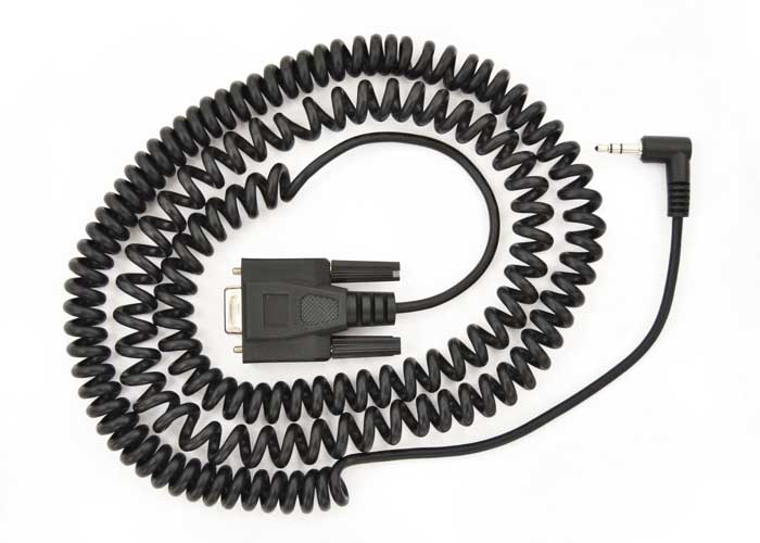
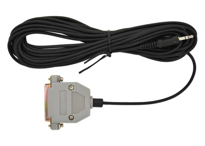
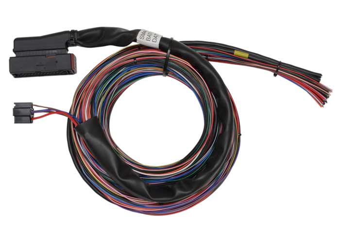
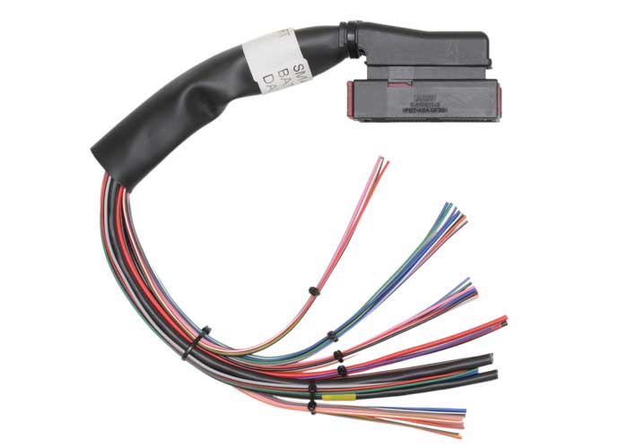
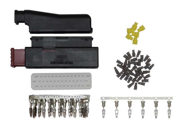
SEQUENTIAL ENGINE MANAGEMENT SYSTEM
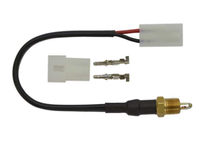
(also available as a short loom, long loom or connector set kit with air temperature sensor, data lead and fuel pump relay)
When ordering specify...
(3.0 metre)
(420 mm)
temperature sensor